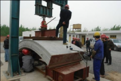
Compression Tester
Shield Tunnel Segment Bending Testing Machine / Segment Pull-out & Leakage Inspection Testing Machine
Brand:EST TEST INSTRUMENT
Product origin:SHANDONG, CHINA
Delivery time:Delivery within 7 working days after receipt of the payment
Supply capacity:Annual output 500 units
Email:estsyj@163.com
Send Inquiry Now
Shield Tunnel Segment Bending Testing Machine / Segment Pull-out & Leakage Inspection Testing Machine
Product Overview
The precast concrete segment bending & pull-out testing machine / segment leakage inspection testing machine is designed and manufactured in accordance with GB/T22082-2008 Precast Concrete Lining Segments and CJ/T164-2011 Technical Standard for Quality Inspection of Shield Tunnel Segments, mainly used for bending performance and pull-out performance inspection of segments. During operation, push the segment onto the trolley and move it into the bending and pull-out space; push the trolley out after testing is completed.
Bending Performance Inspection
Detect bearing capacity of segments to check whether bearing capacity complies with design requirements. Push the segment into the testing machine and apply load stepwise with jacks at 10kN per stage, static hold for 1 minute and record displacement deformation at each measuring point.
Pull-out Performance Inspection
Also adopt stepwise loading with jacks to increase pull-out force step by step and record pull-out resistance.
Main Technical Indicators of Precast Concrete Segment Bending & Pull-out Testing Machine / Segment Leakage Inspection Testing Machine
1. Maximum test force: 1000kN
2. Test force measurement range: 2%~FS, full range without grading; indication accuracy: ±1%
3. Displacement measurement range: 0~200mm; resolution: 0.01mm
4. Test speed: 0.5mm/min–100mm/min; full load test speed: 50mm/min
5. Auxiliary fixtures: Distribution beam: approx. 1800mm×500mm×400mm; Support roller: approx. 1800mm×240mm×350mm; Support trolley: approx. 1800mm×800mm×400mm
6. Adjustable test space (with fixtures and trolley): 1200mm
7. Lower platform length of main machine: 6000mm
8. Clear distance between columns: 2000mm
9. Piston stroke: 200mm
10. Overall host dimensions: approx. 2350mm×6000mm×2580mm
11. Control cabinet dimensions: 1150mm×665mm×860mm
12. Hydraulic power station: 7L/min, 26MPa, 4kW, three-phase AC380V, air cooler built-in
13. Control system: Full digital electro-hydraulic servo control, supporting multiple control modes including constant test force speed, constant displacement, test force holding and displacement holding
Bending Test Methods
Requirements for Concrete Segment Bending Performance Inspection Device
1. The reaction force provided by the loading reaction frame shall not be less than 1.2 times the maximum test load.
2. The trolleys supporting both ends of the concrete segment can roll along ground tracks.
3. Hydraulic jacks should be adopted for loading and unloading.
4. Load applied to the concrete segment shall be realized via load distribution beams with loading points at 1/3 of the segment span.
5. The length of pressure bars shall be equal to the segment width.
Installation Requirements for Concrete Segment Bending Performance Inspection Equipment
1. Place the segment stably on the inspection frame and pad rubber mats with thickness not less than 20mm at loading points.
2. Arrange deflection and horizontal displacement measuring points during segment inspection.
3. Hydraulic jacks are recommended for graded loading and unloading.
Selection of Measuring Instruments for Concrete Segment Bending Performance Inspection
1. Load measuring system can adopt direct measurement via load tester or measure via jack pressure gauge.
2. Displacement should be measured with dial indicators (mechanical or digital).
3. Cracks should be measured with reading microscopes.
Test Methods
1. Adopt graded loading for concrete segment bending performance inspection; each load stage shall maintain for no less than 5min, record displacement variation at each measuring point under each load stage and apply the next load stage.
2. Considering self-weight of testing equipment and segment, initial loading load is 30KN, each load stage increases by 10KN and maintains for 5min to record pressure gauge readings and displacement variation at center point, loading point and horizontal measuring point.
3. Stop loading for 10min after cracks appear on the concrete segment to observe crack development, and take the load value of this stage as measured cracking load.
4. Maintain load for 30min after loading to design load, observe crack development and record maximum crack width, then unload and terminate testing.
Data Processing of Concrete Segment Bending Performance Inspection
1. Calculate displacement variation at each load stage in accordance with formulas.
2. Draw charts of center point displacement, loading point displacement, horizontal displacement vs load.
3. Provide position, length and width diagrams of cracks at each load stage.
Test Failure Judgment (Re-test Required)
1. Abrupt abnormal mutation of displacement variation curve.
2. Local damage of concrete segment at loading point.