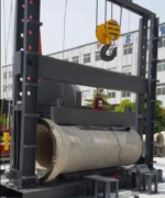
Compression Tester
Reinforced Concrete Drainage Pipe Compression Testing Machine
Brand:EST TEST INSTRUMENT
Product origin:SHANDONG, CHINA
Delivery time:Delivery within 7 working days after receipt of the payment
Supply capacity:Annual output 500 units
Email:estsyj@163.com
Send Inquiry Now
Reinforced Concrete Drainage Pipe Compression Testing Machine
Product Overview
The concrete drainage pipe internal pressure testing machine is used to detect internal water pressure performance of concrete and reinforced concrete drainage pipes, complying with GB/T 11836-99 Concrete and Reinforced Concrete Drainage Pipes and GB/T 16752-2010 Test Methods for Concrete and Reinforced Concrete Drainage Pipes.
Technical Parameters
1. Inner diameter range of test pipes: 1200mm–3000mm
2. Length range of test pipes: ≤2300mm
3. Internal water pressure: 0–0.1MPa, minimum resolution: 0.01 MPa, manual control of constant pressure time (constant pressure >3min)
4. Rubber plate thickness: 2mm
5. Pipe lateral displacement device: 1 set
6. Overall host dimensions: approx. 5000×4000×4000mm
7. Installed capacity: 1.1KW (fast water injection speed)
8. Pressure adjustment mode: Water pump pipe water injection type (horizontal)
9. Applicable concrete pipe types: Flat mouth type and socket type
10. Pressure holding mode: Digital display, set upper and lower pressure ranges in advance for automatic pressure holding
Operation Steps
1. Switch on the power supply; place the drainage pipe on the lower compression platen, push the lower compression platen into the reinforced concrete drainage pipe compression testing machine and align the center.
2. Hang or remove corresponding weights on the pendulum rod according to the required measurement range of the drainage pipe, align the scale line on the buffer valve handle with the marking line, and wind recording paper on the recording drum (these two steps can be performed simultaneously).
3. Start the oil pump, unscrew the oil delivery valve to lift the lower platen wheels about 10mm off the track, zero the active and passive needles, and close the oil delivery valve.
4. Start the crossbeam motor to lower the upper platen to about 10mm away from the specimen, then turn the handwheel on the crossbeam to bring the upper platen into contact with the specimen. Slowly unscrew the oil delivery valve to apply load at the test-specified loading speed. After the specimen is crushed, close the oil delivery valve and stop the oil pump motor, record the required load value and lift the drawing pen. At this time, unscrew the oil return valve to lower the lower platen and take out the crushed specimen. Repeat the above steps to complete tests of other specimens.
5. After all specimens are tested, remove debris, wipe the reinforced concrete drainage pipe compression testing machine and restore it to original condition. Register usage in the logbook after each test.