Automotive Component Fatigue
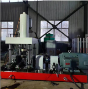
Bearing Bush Fatigue Testing Machine / Engine Bearing Bush Wear & Durability Testing Machine
Brand:EST TEST INSTRUMENT
Product origin:SHANDONG, CHINA
Delivery time:Delivery within 7 working days after receipt of the payment
Supply capacity:Annual output 500 units
Email:estsyj@163.com
Send Inquiry Now
Bearing Bush Fatigue Testing Machine / Engine Bearing Bush Wear & Durability Testing Machine
1. Product Introduction
The electro-hydraulic servo bearing bush wear fatigue testing machine is specially designed to measure long-term wear performance as well as dynamic and static mechanical properties of alloy bearing bushes for automobile engines under alternating loads.
The 400kN electro-hydraulic servo bearing bush wear fatigue tester is developed under the design philosophy of "unitization, modularization and standardization". It integrates mature electro-hydraulic servo dynamic testing machine technologies and is optimized according to actual operation demands of domestic customers. Key auxiliary components of the electro-hydraulic servo dynamic system adopt high-quality domestic equivalent parts, which greatly improves the stability and reliability of the whole system. Core modules and components are manufactured with state-of-the-art technologies, making the overall performance of this test system comparable to mainstream dynamic test equipment from professional manufacturers.
This series features easy operation, high control precision and outstanding reliability. The 400kN electro-hydraulic servo bearing bush wear fatigue tester is one of our self-developed dynamic-static universal test equipment. Core components including the main frame, constant-pressure servo hydraulic station and spindle box are independently designed and manufactured by our factory. Critical purchased parts such as servo valves and sealing elements are sourced from premium suppliers to further enhance system stability and reliability, with overall performance reaching industry-leading standards.
2. Main Structure & Functions of Automobile Bearing Bush Fatigue Tester
The 400kN electro-hydraulic servo dynamic bearing bush wear fatigue testing machine consists of the following assemblies:
1. Main frame equipped with a top-mounted 400kN servo linear actuator and rotary driving unit;
2. Spindle box, test fixtures and their hydraulic driving modules;
3. Constant-pressure servo hydraulic station (flow rate: 40L/min, system working pressure: 21MPa);
4. Full-digital single-channel servo controller;
5. Industrial computer, printer, dedicated test software and other necessary auxiliary accessories.
3. Technical Specifications
1. Maximum static test force: ±500kN; static force indication accuracy: ±0.5% full range (non-step division)
2. Maximum dynamic test force: ±400kN; dynamic force fluctuation: ≤±0.5%
3. Maximum actuator stroke amplitude: ±50mm; stroke indication accuracy: ±0.5%
4. Frequency range: 0.01–80 Hz
5. Displacement measurement accuracy: ±0.5% reading (non-step full range)
6. Displacement sensor resolution (magnetostrictive sensor): 0.01 mm
7. Multi-segment function generator built-in
8. Cycle counter: up to 999,999,999, presetable
9. Control modes: load control, displacement control, deformation control; supported test waveforms: sine wave, square wave, triangular wave, ramp wave
10. Maximum measurable test torque: 1500 N·m
11. Clear distance between columns: 600 mm
12. Main frame rigidity: 3.3×10⁸ N/mm
13. Rotary motor power: 75 kW
14. Overall dimension of main frame: approx. 1900×700×2160 mm (L×W×H)
15. System working pressure: 21 MPa
16. Constant-pressure servo hydraulic station parameters: flow rate 40 L/min, rated pressure 21 MPa, motor power 18.5 kW, rotating speed 1450 r/min
17. Spindle rotating speed: 200–4000 rpm
4. Lifting, Transportation & Storage
4.1 Lifting Requirements
When lifting the machine, align the lifting position properly to keep the gravity line perpendicular to the ground. Control lifting speed at a low level to prevent tilting or loose assembly, which would impair the machine’s measurement accuracy.
4.1.1 Main Frame Handling
Remove fixing timbers after unpacking the main frame. Hook lifting eyebolts only, lift the machine slowly, raise it to the designated height then lower it gently to the installation position, and assemble per the assembly drawing.
4.1.2 Electronic Control System
Handle the computer system and controller with care. Keep the correct top-bottom orientation to prevent loose wiring.
4.2 Storage Requirements Before Unpacking
Store the packaged equipment in a dry, well-ventilated shelter free from direct sunlight and rain exposure, to avoid rust formation and guarantee stable operation and measurement precision of the tester.